Have you ever wanted to digitize real-world objects with precision but found commercial 3D scanners too expensive? Building your own 3D laser scanner is not only possible, it is surprisingly accessible. Using a simple setup of a webcam, line laser, and rotating turntable, you can reconstruct detailed 3D models through laser triangulation, a method trusted in industrial and academic applications. This guide walks you through every step from assembling hardware and calibrating the system to capturing laser profiles, reconstructing point clouds, and exporting printable OBJ files.
Core Scanning Principle: Laser Triangulation

How 3D Laser Scanning Works
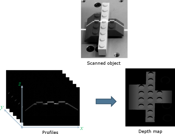
A 3D laser scanner captures object geometry by projecting structured light and analyzing its deformation. The core technique is optical triangulation. A line laser casts a red stripe across the object surface. A camera, offset at a fixed angle, records how the laser line bends with the contours. Each pixel on the laser line corresponds to a 3D point found by intersecting the camera ray from the lens to the pixel with the known plane of light from the laser. This generates one 2D profile per image. To build a full 3D model, rotate the object on a turntable and merge successive profiles.
Active vs. Passive 3D Scanning
Unlike photogrammetry which relies on ambient textures, active illumination ensures reliable data regardless of surface color. Laser-based scanning works on black, white, or featureless objects. It eliminates ambiguity in low-contrast areas where stereo vision fails. Controlled lighting improves edge detection and point accuracy. This makes laser scanning ideal for smooth or uniformly colored items like figurines, tools, or prosthetic components.
Essential Hardware Components for Your Scanner
Required Equipment List
You need six core components to build a functional 3D laser scanner. A camera captures laser deformation, such as a Logitech C920 or Raspberry Pi Camera Module. A line laser projects structured light, like a 650nm AixiZ module. A turntable rotates the object incrementally, either a manual lazy Susan or stepper motor stage. A computer runs software and processes data on Windows, Mac, or Linux. An enclosure, which is optional, reduces ambient light interference. A calibration target enables geometric accuracy, typically a checkerboard printout or foam board.
Choosing the Right Line Laser
Pre-built line lasers use a 650nm AixiZ diode with a cylindrical lens for even, straight projection. For a DIY approach, place a wine-glass stem or glass rod in front of a point laser. Refraction spreads the beam into a clean line. Red wavelength 650nm is cheapest and most visible. Avoid high-power lasers above 5mW. Class II lasers at 1mW or less are eye-safe and sufficient for indoor scanning.
Turntable Options: Manual vs. Motorized
A manual turntable involves rotating the object by hand between captures, like a lazy Susan. This option is low cost but less consistent. A motorized turntable is driven by a stepper motor and Arduino or Raspberry Pi. It rotates in precise steps, typically 5 to 15 degrees. For automated scanning, pair the motor with a microcontroller to trigger image capture at each angle.
Software Tools and Processing Pipeline
Top Software for DIY Scanning
David Laser Scanner provides a full GUI with calibration, scanning, and export features. The basic version is free, and a paid Pro version adds auto-alignment and noise removal. OpenCV with Python enables custom real-time processing and is open-source. Blender handles mesh cleaning, alignment, and rendering, and it is free. Fusion 360 or CorelDRAW helps design enclosures and mounts, with free trials available.
Output File Formats and Compatibility
OBJ Wavefront Object is the standard format storing vertices, faces, and texture. Exported OBJ files can be 3D printed via Cura or PrusaSlicer. They can be imported into CAD software like Fusion 360 or SolidWorks. They work in game engines such as Unity or Unreal. They can be shared via email or web viewers like Three.js.
Step-by-Step Calibration Process
Calibrate Camera Intrinsics First
Before scanning, determine internal camera parameters including focal length, principal point, and lens distortion. Print an 8 by 6 checkerboard pattern. Capture 10 to 20 images at various angles and distances. Use software like David or OpenCV to detect corners and compute the intrinsic matrix K.
Determine Camera Pose Extrinsics
Extrinsics define the camera position and orientation relative to the world. The mathematical foundation uses the projection equation where lambda u equals K times R p plus T. Here u is the 2D image point, p is the 3D world point, K is the intrinsic matrix, R is rotation, and T is translation. Solve via linear estimation like SVD and refine with nonlinear optimization. Once calibrated, the camera view remains fixed, so do not move it during scanning.
Find Turntable Rotation Center
This is critical for accurate profile alignment, especially with manual turntables. Attach a CALTag checkerboard with unique binary codes per cell to the turntable. Capture images at multiple angles. Track visible corners to estimate the center and rotation angles. Even without encoders, this method aligns scans by calculating angular offsets from visual data.
Calibrate the Laser Plane
The laser defines a known 3D plane used in triangulation. Calibration finds its equation. Place a checkerboard on the turntable and tilt it at several angles. Capture laser line intersections. For each image, detect laser pixels and triangulate 3D points using ray-plane intersection. Fit a least-squares plane to all points. Use the same checkerboard images for both intrinsic and light plane calibration to save time.
Laser Detection and Image Processing Techniques
Detecting the Laser Line in Color Images
On white or shiny objects, simple red-channel thresholding fails because white surfaces reflect red too strongly. The problem is that direct max-red detection leads to incorrect 3D points when white objects show stronger red intensity than the actual laser line.
Solution: Channel Difference Filtering
Use this formula to isolate true laser pixels. Calculate I diff equals I red minus the average of I green and I blue. This enhances areas where only red is bright, like the laser, while suppressing white and ambient reflections.
Laser Stripe Detection Algorithm
Compute I diff for each frame. Apply horizontal Gaussian blur to smooth noise and stabilize peaks. For each image row, find the pixel with maximum I diff and record its x,y coordinate. Output a curve of 2D points tracing the laser line. In rare cases, multiple slits appear due to object holes or reflections. Keep only the brightest segment.
Background Masking for Faster Scans
Speed up processing and reduce errors by excluding static regions. Compute per-pixel intensity variance across all scan images. Low variance indicates background like wall or floor. High variance indicates foreground like the object with moving laser. Create a binary mask to ignore background pixels during triangulation.
Complete Scanning Workflow
Prepare Your Scanning Environment
Darken the room or build an acrylic enclosure. Mount the camera and laser securely and do not move them after calibration. Position the turntable so the laser hits the object side, not the base. Connect all USB devices like camera and motor controller. Use foam board or black fabric as backdrop to reduce reflections.
Position and Secure the Object
Center the object over the turntable axis. Elevate small items on a pedestal to avoid scanning the base. Avoid reflective, transparent, or black matte surfaces. Glossy objects scatter laser light. Clear materials refract the beam. Apply matte spray or talcum powder to problematic surfaces. For full coverage, you need multiple scans from different angles.
Capture Scan Images
Turn on the laser. Rotate the turntable in fixed increments, typically 10 degrees. Capture one image per angle. Software detects the laser line in each frame. With a motorized system, automate rotation and capture via Arduino or Raspberry Pi.
Reconstruct the 3D Model
For each image, triangulate laser points using ray-plane intersection. Rotate points by the inverse of the turntable angle to align in world coordinates. Merge all profiles into a single point cloud. Generate a triangular mesh as the surface model. Only one side is captured initially. Rotate the object and repeat to scan the back.
Real-Time Visualization and Feedback
Live Scanning with Preview
Advanced setups like Raspberry Pi-based scanners offer real-time feedback. Display the live camera feed. Overlay the detected laser line. Show the 3D mesh updating as scans proceed. The processing pipeline includes red-channel filtering, perspective correction, and data reduction to a single-pixel-wide laser trace. This immediate feedback helps adjust alignment and spot scanning errors early.
Post-Processing Your 3D Model with Blender
Import and Inspect the OBJ File
Open Blender. Go to File, Import, Wavefront OBJ. View the raw mesh and expect noise, gaps, or misaligned segments.
Clean the 3D Mesh
Switch to Edit Mode to remove artifacts. Press B to box-select and delete floating fragments. Use Merge by Distance to remove duplicate vertices. Apply Fill Holes to close small gaps. Avoid over-smoothing to preserve fine details captured during scanning.
Align Multiple Scans Manually
If you scanned the object from multiple positions, import each OBJ as a separate object. Use G for grab and R for rotate to align overlapping regions. Zoom in to match key features like edges and corners. The free version of David lacks automatic global registration, so manual alignment is required.
Render Final Output
Set camera angle and lighting. Press F12 to render. Save the image or animation with Ctrl+F12.
Exporting and Using Your Scanned Models
Save and Share Your Scan
Export the cleaned model as OBJ or STL. Email or upload for 3D printing. Embed in web apps using Three.js. Common applications include 3D printing to replicate toys, tools, or custom parts. Reverse engineering to digitize legacy components. Digital archiving to preserve fragile artifacts. Cosplay and props to create wearable replicas. Education to demonstrate 3D imaging in STEM labs.
Performance Tips and Limitations
Strengths of DIY Laser Scanning
High detail captures fine textures and curves. Low cost comes in under $100 with reused parts. Results are repeatable and consistent across scans. The approach is accessible using open-source tools and common hardware.
Key Limitations to Know
The free software lacks auto-alignment, requiring manual mesh merging. Ambient light sensitivity means you need a dark environment. The method performs poorly on reflective or translucent surfaces. Manual effort is required for multiple scans and cleanup to achieve full models.
Pro Tips for Better Scans
Use a dark background to boost contrast. Elevate small objects to avoid base interference. Apply matte spray to shiny surfaces. Scan in 10 to 15 degree steps for smooth rotation. Reuse calibration unless hardware moves.
Building an Enclosure for Better Results
Laser-Cut Acrylic Enclosure
An enclosure blocks ambient light and improves scan consistency. Model a box in Fusion 360. Export vector files to CorelDRAW. Cut with a laser cutter. Include camera and laser mounting holes. Include top access for placing objects. Include ventilation slots if using enclosed electronics. Ensure unobstructed line of sight between laser, object, and camera.
Foam Board Alternative
No laser cutter? Use printable templates instead. Download David calibration PDF where scale 30 equals about 4 inches and scale 100 equals about 12 inches. Print, cut, and fold along the center line at 90 degrees. Tape edge markers for alignment.
Upgrading with Automation and Advanced Features
Automate Rotation with Stepper Motor
Integrate a NEMA 17 stepper motor with Arduino or Raspberry Pi and a DRV8825 driver. Program it to rotate 10 degrees, capture an image, and repeat. This enables unattended, full 360-degree scanning.
Real-Time Mesh Generation
Use Python with Open3D or PCL Point Cloud Library to filter noisy points. Smooth and downsample data. Generate watertight meshes on the fly.
Alternative Detection Methods
Laser-on minus laser-off subtraction works only if the object is stationary. Dual cameras improve coverage and reduce occlusion. Multi-wavelength lasers reduce ambient interference.
Frequently Asked Questions About Building a 3D Laser Scanner
What is the minimum budget for a DIY 3D laser scanner?
You can build a functional 3D laser scanner for under $100 using a basic webcam, a 650nm line laser module, and a manual turntable. The most expensive components are the camera and laser, which together typically cost $30 to $50. Open-source software like David Laser Scanner and Blender are free.
Can I scan shiny or black objects with a DIY laser scanner?
Scanning shiny or black objects is challenging because laser light scatters off reflective surfaces or gets absorbed by dark materials. Apply matte spray or talcum powder to the object surface before scanning. This creates a diffuse coating that the laser can detect reliably.
Do I need programming skills to build a 3D laser scanner?
Programming skills are helpful but not required. David Laser Scanner provides a graphical interface that handles most of the processing automatically. You can start with the basic version and upgrade to the Pro version for advanced features. Python and OpenCV are only necessary if you want to build custom processing pipelines.
How accurate is a DIY 3D laser scanner compared to commercial options?
DIY laser scanners can achieve sub-millimeter accuracy with careful calibration, but they generally do not match the precision of commercial scanners costing thousands of dollars. The accuracy depends on camera resolution, laser quality, calibration precision, and environmental conditions. For hobbyist applications like 3D printing prototypes or digitizing collectibles, DIY scanners provide sufficient detail.
What objects cannot be scanned with a laser scanner?
Transparent objects like glass or clear plastic refract the laser beam and produce incorrect data. Highly reflective surfaces scatter laser light unpredictably. Very dark objects absorb most of the laser energy. Extremely small objects below a few millimeters may exceed the resolution limits of your camera and laser setup.
Key Takeaways for Building Your Own 3D Laser Scanner
Building a 3D laser scanner combines optics, mechanics, and software into a powerful DIY tool. The core principle of laser triangulation lets you reconstruct detailed 3D models using just a webcam, line laser, and turntable. Calibration is the most critical step. You must calibrate camera intrinsics, extrinsics, the laser plane, and the turntable center for accurate results. Use channel difference filtering to detect the laser line reliably, even on white or shiny surfaces. Post-processing in Blender is required to clean and align your scans, especially when using free software. With careful setup and attention to lighting, you can achieve professional-grade results at a fraction of the commercial cost. Start simple with a webcam and laser pointer, then expand with automation and better optics. Your homemade scanner opens a new dimension of creation for prototyping, preserving artifacts, or exploring 3D imaging technology.